
♥♪ Heartbeat Issue 2.0.0
Over the past week I finalized the pcb schematics for the Pixel PCB and began ordering the components necessary to prototype the electronics. What follows is the result of many emails, phone calls, and a lot of time spent in IRC.
This is the second Pixel Heartbeat.
Ordering Prototypes
Issue 2.0.0: October 3rd-10th, 2014
This newsletter outlines progress of the new Pixel Heart in five major categories:
Summary
- I now understand how the Worldsemi circuit’s transistors and WS2811 magic works.
- I’ve initiated a small prototype batch of PCBs.
- An initial batch of the PCB parts has been ordered.
- I will likely be thermoforming the cases rather than plastic injecting them.
- I received 5 of the Worldsemi boards to test - here’s a video of them in action:
Goals for next week:
- Assemble the first pcb prototype.
- Test the light diffusion against the polycarbonate compound sample.
PCB Design
I was fortunate enough to stumble upon the Worldsemi 12-lamp LED circuit a few weeks back, but had no idea how it worked. In order to confidently design the PCB I wanted to understand why all of the parts were necessary, so I spent some evenings in the afternet #electronics and #sparkfun IRC channels asking questions.
Two questions from Heartbeat 1 were resolved as a direct result.
Answer: why does the original schematic contain a 5V power line?
The answer is simple, but unclear: within the WS2811 is likely a zener diode that allows it to turn a 12V or 24V VDD into the 5V needed to drive the IC. This is accomplished by placing a resistor in series from the VDD to the WS2811 and then branching off from that connection. As far as I can understand this works, in principle, like voltage division.
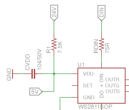
The zener diode is hinted at in the WS2811 datasheet:
Built in stabilivolt, only add a resistance to IC VDD feet when under 24V power supply.
Not super clear.
I received five of the WS2811 Worldsemi units this week and poked them with my multimeter to see what was going on. I verified that the board was running 5V along the transistors, putting to rest any questions about whether the 5V was a typo in the original schematic.
Answer to: why does each RGB color line need two transistors?
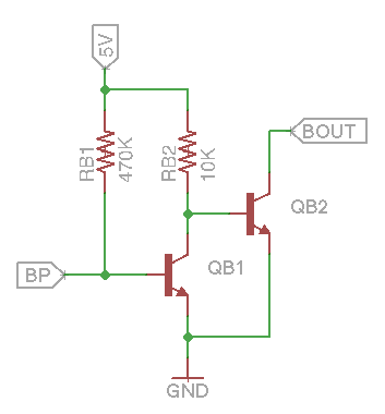
In order to understand this transistor diagram I had to relearn some of the basics of electronics. I spoke with multiple people before I finally found someone (sgrace from the #sparkfun channel) who understood what was going on in this schematic.
To begin, sgrace referred me to this simulation of the schematic. Warning: needs a java plugin - if you’re on a Mac use Safari.
Notably there are two states in the schematic. LEDs powered on:
And LEDs powered off:
Seeing the animation wasn’t enough for me to understand, however, so sgrace pointed out the following important concepts to consider:
The WS2811 color pins are PWM sinks, meaning when they’re OFF, electricity runs toward them as though they’re Ground, but when they’re ON they’re effectively open circuits.
My original mistaken understanding was that the WS2811’s pins were generating current in the ON state.
The WS2811 PWM sinks can safely handle 18.5mA of current. Transistors allow us to power a bigger current - e.g. LEDs that are drawing more than 18.5mA - from the WS2811.
So given these two facts, let’s look at the LEDs powered ON simulation once more.
LEDs ON
In this simulation the WS2811 is in its OFF state and acting like a Ground.
The 5V electricity flows directly to the WS2811 (represented here by the 25Hz) rather than powering the left-most transistor. I’ve singled out the path of the electrons in the following image:
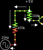
With the left-most transistor closed, the 5V electricity can only flow to the right-most transistor, opening it and allowing current to flow through the LEDs.
LEDs OFF
The OFF simulation is just the opposite, as you’d expect.
In the WS2811 ON state it effectively removes itself from the circuit.
Electricy is lazy. So the laziest thing for the 5V electricity to do here is to open the first transistor. With the first transistor open, there is a direct connection from the 5V line to the true Ground, and this is preferred over flowing the second transistor. Because of this, the second transistor remains closed and the LEDs don’t turn on.
Even after explaining it it still seems like magic to me. How does the electricity “know” what the laziest path is? And how is it doing this seemingly instantaneously?
Answer to: what will be the optimal LED arrangement?
Figuring this out involved some basic trig.
From the 5050 LED datasheet I found out that their lighting angle is 120°.
We want to calculate the radius spread of the light for a given height. So we draw some lines and angles to get the following diagram:
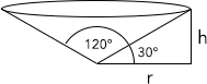
We can calculate r using trig:
Theta in this case is 30°, so the lighting spread for various heights in mm is:
| height | radius | diameter |
|---|---|---|
| 3 | 5.20 | 10.39 |
| 5 | 8.66 | 17.32 |
| 6.4 | 11.09 | 22.17 |
| 7 | 12.12 | 24.25 |
If we turn these diameters into pixel units and plot them in Photoshop on a 3x3” equivalent grid, we get the following lighting spreads:
3mm

5mm

6.4mm

7mm

Based on these estimates it looks like I’ll need at least 6.4mm in order to start seeing overlap of the LEDs and to avoid hotspots. The diffuse material might diffuse the light further than these estimates, but I’ll need to verify that with the actual product.
Answer to: are 12 LEDs too much? Can I get away with just 6?
For now it looks like I’ll need 12 LEDs in order to keep the form factor of the cases minimal. With only 6 LEDs I might need a case that’s more than 7mm away from the board.
New Progress
Since last week I completed the first version of the Pixel Heart schematic, shown below.
![]()
And the corresponding board:
![]()
Misc notes:
- I’ve touched up and documented the original Worldsemi schematic in order to clarify what’s going on with the transistors and 5V line.
- I kept the single-layer routing found in the original board in order to keep costs down for the PCB manufacturing.
- The LEDs have been rearranged on a grid, rather than circularly. This is to maximize the lighting spread across the entire board.
- The board is smaller at 2.9” compared to Worldsemi’s 3.25”, making the board a bit tighter overall.
No open questions.
PCB Fabrication
I sent the finished PCB project to a fabrication shop (golabo) in Montreal to get some prototypes made. They should be finished by next Friday. I requested 10 PCBs to be made and it will cost me $150 CAD. Pretty steep compared to other estimates I’ve gotten for big batches, but they’re local and I’m hopefully going to visit on Monday in order to learn more about the process.
No open questions.
PCB Assembly
Earlier this week I ordered all of the necessary parts to build the first prototypes of the PCBs. I ordered my parts from three separate sources:
Digikey Parts
| Quantity | Part Number | Manufacturer Part Number | Unit Price | Total Price |
|---|---|---|---|---|
| 12 | 311-7.5KERCT-ND | RC1206JR-077K5L | 0.02400 | $0.29 |
| 50 | P470KECT-ND | ERJ-8GEYJ474V | 0.02760 | $1.38 |
| 50 | P10KECT-ND | ERJ-8GEYJ103V | 0.02760 | $1.38 |
| 50 | P75ECT-ND | ERJ-8GEYJ750V | 0.02760 | $1.38 |
| 25 | 311-910ERCT-ND | RC1206JR-07910RL | 0.01760 | $0.44 |
| 50 | P300ECT-ND | ERJ-8GEYJ301V | 0.02760 | $1.38 |
| 25 | 311-1435-1-ND | CC1206JRX7R9BB104 | 0.09040 | $2.26 |
| 100 | MMSS8050-H-TPMSCT-ND | MMSS8050-H-TP | 0.11870 | $11.87 |
Total Cost: $20.38 + $20 shipping = $40.38 USD.
I got killed on shipping because I’m in Canada right now, but so it goes.
Sparkfun Parts
I ordered 100 5050 RGB LEDs from Sparkfun for a total cost of $40 + $8.76 shipping = $48.76 USD. I also ordered a teensy3.1 because I’d like to experiment with using them to drive the pixels.
Adafruit Parts
Adafruit carries the WS2811 IC in SOP-8 form so I ordered 10 for $4.95 + $9.15 shipping = $14.10 USD.
Answer to: what other tools and equipment will I need to invest in for assembly?
I still haven’t found a company that can assemble 1600 boards for any sort of reasonable price, so I’m collecting the list of tools and equipment I’ll need in order to do this myself. Thus far the list includes:
- TM-240A Pick and Place Machine ($5500 USD)
- PCB Stencils
- Solder Paste
- Solder Scrapers
- A skillet from Target/Walmart
No matter how I look at it, the assembly costs are expensive and account for roughly 2/3 of the total cost of the electronics. I haven’t seriously looked into doing assembly in China yet, but this might be an avenue I have to pursue if I want to minimize costs.
I have a newfound respect for why things are so damn expensive when they’re made in North America.
Plastic Molding
Since last week I’ve learned much more about the thermoforming process. Notably, it’s much more economic to make large batches of simple molds. I’ve sent out requests for quotes to a few thermoforming companies this week but they’ve yet to get back to me.
The only progress on the mold this week is that I’m likely going to do away with the screw holes in the corners of the case, opting to use an adhesive material to attach the pcbs to the cases. This has the added benefit of also waterproofing the cases.
I haven’t played with Rhino3D yet.
Plastic Manufacturing
Given that I’m likely going the thermoforming route, I’ve had to switch up the diffusion material. I’ll likely go with the Acrylite LED product which is comparably priced to the polycarbonate compound I was previously considering.
Closing Thoughts
Answer to: how will I connect the PCBs to one another?
The cheapest connectors I’ve been able to find are these 4-pin JST plugs from Alibaba, running at $0.45 a pair. I like these because it will allow me to plug/unplug the pixels at will.
Answer to: how will I power this setup?
I’m likely going to purchase 8 of these 648W 24V PSUs for a total cost of $826.70 USD.
Answer to: how will I control the lights?
There are a number of existing DMX controllers out there to control WS2811 pixels, but they’re crazy expensive. Instead, I’m going to experiment with a combination of Arduino/Beagles/Raspberry PI to distribute the lighting control over an ethernet network. Another option is to simply do as I did with Pixel Heart v1 and power the whole thing off a simple USB FTDI adapter - but this means that I won’t be able to drive the lights with generic lighting software.
General open questions:
-
What mechanisms can be used to attach pixels to one another? I’d love to be able to, say, wrap the pixels around a surface, or have some distance between any two pixels.
-
What mechanisms can be used to hold the pixels up a-la Pixel Heart v1 (12x8’ of beating hearts and swirling colors)?
-
Will I be better off just ordering the already-made Worldsemi pcbs and getting them made as squares? In order to answer this I need to test the circular LED arrangement with the diffuse material to ensure there aren’t any noticable hotspots.
Current estimate on v2 completion: still maybe by next burning man.
Thanks for reading, hope you learned something new!
♥beats